Case study 02
1 MW Solar Grid-Connection Assessment
Evidence verified - sanitised write-up
Technical assessment for connecting a 1 MW solar plant to the SA Power Networks distribution grid: connection voltage, power-quality compliance, protection, and storage, decided against AS/NZS inverter standards and SAPN TS132/TS133.
| Inverter AC nameplate | 1.0 MW | the rated AC output assumed for the assessment |
|---|---|---|
| PV array DC capacity | ≈1.2 MWp | installed module capacity; exceeds the inverter rating at a ~1.2 inverter loading ratio |
| Approved export limit | ≤1.0 MW | possibly below the inverter rating; set by SA Power Networks after the connection study |
| Connection voltage | LV (TS132) or HV (TS133) | decided by a site-specific network study, not by capacity |
| Standards | SAPN TS132/TS133 · AS/NZS 4777.2 |
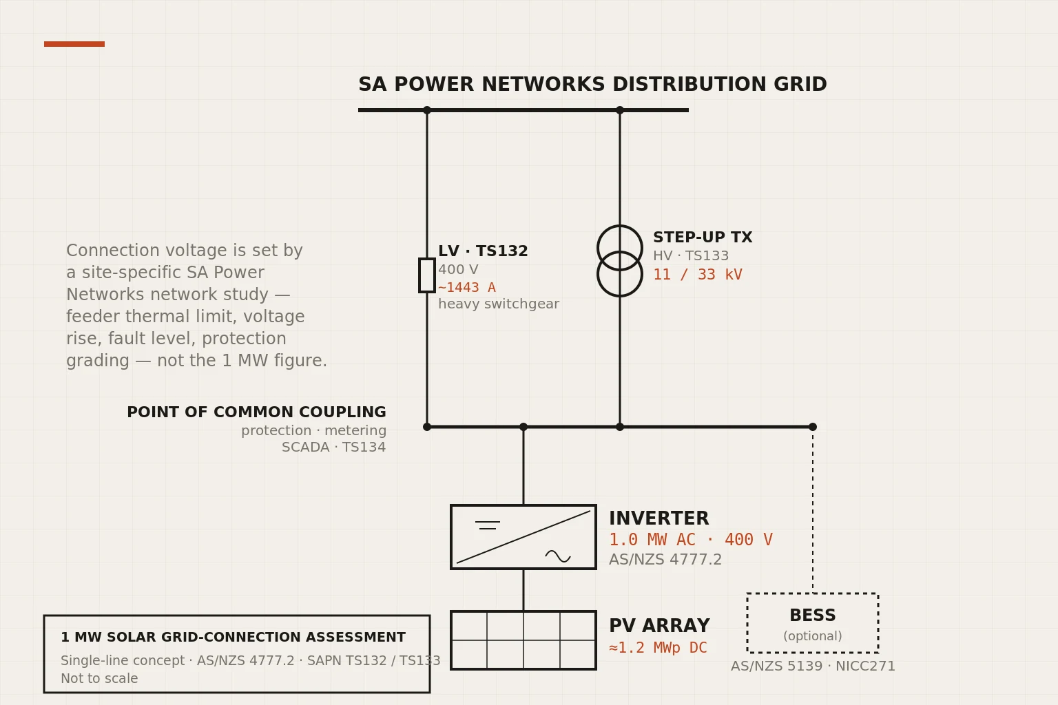
Open the full-size diagram (opens in a new tab)
Problem
What needed solving
Determine how a new 1 MW solar plant could be connected to the SA Power Networks distribution grid (the viable connection voltage, the power-quality and protection obligations, and whether storage is warranted), and justify each conclusion against the controlling standards and network requirements.
Approach
How the work is framed
Framed the connection against SA Power Networks TS132/TS133/TS134 and the AS/NZS inverter, PV and wiring standards (4777.1/4777.2, 5033, 3000, 61000.4.7): compared LV and HV connection options, tested the reactive-power, frequency ride-through, anti-islanding and harmonic obligations at the point of common coupling, and weighed a battery energy storage system against curtailment, export limits and possible FCAS value.
Result
Current public outcome
A 1 MW AC plant (roughly a 1.2 MWp array at a ~1.2 inverter loading ratio) can connect at LV under TS132 where feeder hosting capacity allows, but an HV connection under TS133 (11 kV or 33 kV) is usually more practical given the export current, voltage-rise and protection demands. The governing finding is that connection voltage and viability follow a site-specific network study (feeder thermal limit, voltage rise, fault level, protection grading), not the plant's capacity or nearby consumer demand; the analysis reframed an early demand-matching assumption toward hosting capacity as the real constraint.
Evidence status
What still needs proof
Verified. Sanitised public write-up complete; coursework is university-generated and unrestricted, and standards tables are cited by clause and number rather than reproduced (Standards Australia copyright).
Assessment detail
The connection assessment
This is a technical assessment of connecting a 1 MW solar plant to the SA Power Networks distribution grid: the viable connection voltage, the power-quality and protection obligations, and whether battery storage is warranted. Every conclusion is argued against the controlling standard or network requirement. The write-up is sanitised from graded coursework (university-generated and unrestricted), and standards content is cited by clause and number, not reproduced, because those tables are Standards Australia copyright.
Three capacities, not one number
“1 MW” is ambiguous until it is split into three separate figures, the confusion that most affects the connection design. The assessment tracked each independently:
| Capacity | Value | Basis |
|---|---|---|
| PV array DC capacity | ≈1.2 MWp | Installed module capacity; exceeds the inverter rating at a ~1.2 inverter loading ratio. |
| Inverter AC nameplate | 1.0 MW | The rated AC output assumed for the assessment. |
| Approved export limit | ≤1.0 MW | Maximum power permitted into the network at the point of common coupling, set by SA Power Networks after the connection study, possibly below the inverter rating. |
Connection voltage: LV under TS132 or HV under TS133
A 1 MW system does not automatically require a High Voltage connection. Under SA Power Networks TS132, Low Voltage embedded generation may be possible where the local feeder has sufficient hosting capacity and voltage rise stays within limits. But at 400 V a 1 MW three-phase export draws very high current, demanding substantial dedicated switchgear, cabling and transformer capacity, so an HV connection under TS133 (typically 11 kV or 33 kV) is often more practical: lower current, better voltage control, simpler protection coordination.
Why HV is usually more practical at 1 MW
  LV (TS132)   ~1443 A at 400 V 3-phase export  → heavy switchgear/cabling
  HV (TS133)   11 kV or 33 kV                    → lower current, easier
                                                   voltage + protection

Connection voltage is NOT chosen by capacity alone. It is set by a
site-specific SA Power Networks study of:
  feeder thermal limit | voltage rise | fault level |
  protection grading   | available transformer capacity
The final connection voltage cannot be selected from plant capacity; it must be determined by SA Power Networks through a site-specific study. The plant would also need switchgear, ring main units, breakers, isolators, instrument transformers and protection relays at the point of common coupling, plus metering, telemetry and SCADA-compatible communications to TS134 where required.
Power-quality and protection obligations
Reactive power. Output must be controlled to hold network voltage stable; SA Power Networks may require fixed power factor, Volt-VAr response, voltage control, export limiting or SCADA reactive-power setpoints. The inverter must supply or absorb reactive power across the required range; Volt-VAr control trims reactive output against local voltage during high export and low local demand.
Frequency ride-through versus anti-islanding: distinct functions. On a nominal 50 Hz grid, the inverter must ride through permitted frequency excursions to avoid nuisance tripping on short disturbances. Anti-islanding is the opposite case: if the mains supply is lost, the generator must detect the abnormal condition and disconnect within the safe timeframe so it cannot energise an isolated network section. Ride-through applies while the grid is present; anti-islanding applies when it is gone.
Harmonics.Inverters inject harmonic currents, and distortion at the point of common coupling must stay within SA Power Networks limits to avoid heating, nuisance tripping and transformer resonance. AS/NZS 61000.4.7 provides the measurement method for harmonics and THD, but compliance is set by the network's power-quality limits, not the measurement method alone. Mitigation, if needed: low-harmonic inverter selection, active or passive filters, transformer-impedance review or revised control settings.
The revision: hosting capacity, not consumer demand
The assessment began from an intuitive framing: that a plant's viability depends on nearby consumer demand to absorb the generation. That assumption was overturned. Suitability is governed by feeder hosting capacity (feeder impedance, transformer loading, voltage limits, existing solar penetration, protection settings), not by demand alone. Residential feeders carry a higher voltage-rise risk because solar peaks midday when residential demand is low, so export can be curtailed even where demand exists elsewhere; industrial and commercial feeders are often more suitable because daytime demand is higher. Curtailment is mainly a technical constraint (voltage rise, thermal limits, feeder congestion, protection coordination) rather than a simple shortage of consumers.
Why this binds harder in South Australia
The hosting-capacity conclusion is sharper here than in the general case. South Australia carries the highest share of rooftop solar in the country, and AEMO has reported it as the first gigawatt-scale grid in the world to reach zero operational demand, when distributed generation briefly exceeded all local customer load. The midday condition this assessment treats as the limiting case — high PV output against low local demand — is therefore not an edge case on many South Australian feeders; it is a recurring operating state. SA Power Networks already operates a solar curtailment mechanism for minimum system demand events, which is the same constraint this assessment reaches from the connection side: what limits a new 1 MW plant is voltage rise, feeder hosting capacity and minimum-demand management where it connects, not the plant's nameplate.
Storage and hybridisation
A battery energy storage system may be recommended where network studies, export constraints or commercial modelling justify the cost: it absorbs excess midday generation, discharges into evening demand, reduces curtailment, and may provide Frequency Control Ancillary Services if registered, metered and controlled under AEMO rules. If included, it must comply with AS/NZS 5139 and the relevant SA Power Networks BESS requirements (NICC271 where applicable). Wind can complement solar where the resource suits and lift capacity factor, but adds planning, mechanical, noise and grid-connection burden; a gas peaking plant was not preferred (it raises emissions against the renewable objective) and would be considered only where firm backup is specifically required.
Standards and regulatory basis
Installation to AS/NZS 3000 (wiring, earthing, protection). Inverter energy system installation to AS/NZS 4777.1; inverter performance (grid support, anti-islanding, reactive power) to AS/NZS 4777.2. PV-array installation and safety to AS/NZS 5033; battery systems to AS/NZS 5139; harmonic measurement to AS/NZS 61000.4.7. SA Power Networks documents apply: TS132 (LV embedded generation above 30 kVA), TS133 (HV embedded generation), TS134 (communications), the Service and Installation Rules, NICC270 (large embedded-generation documentation) and NICC271 (BESS connection). The Office of the Technical Regulator holds electrical safety and technical compliance in South Australia.
Declared assumptions and limits
The connection voltage, export limit and protection settings are all contingent on a formal SA Power Networks embedded-generation application and site-specific network study; the figures here are the design position, to be confirmed against that study. The recommended next step is that application: single-line diagrams, inverter specifications, protection settings, proposed export limits, a power-quality assessment, communications requirements and BESS documentation where storage is included. This write-up is sanitised from university-generated coursework; no standards table content is reproduced, and no employer, SA Power Networks or Office of the Technical Regulator confidential material is involved.
Questions about this design? nathannoott@gmail.com