Case study 01
Commercial LV Cabling Design
Evidence verified - sanitised write-up
Standards-traceable 400 V cabling design for a three-tenancy commercial complex: maximum demand, cable selection, earthing, and fault verification to AS/NZS 3000 and AS/NZS 3008.1.1.
| Voltage system | 400 V 3-phase | 230 V line-to-neutral |
|---|---|---|
| Design current | 123.6 A | on the heaviest phase (A) |
| Voltage drop | 0.74 % | consumer mains, against the 1 % limit |
| Standards | AS/NZS 3000:2018 · AS/NZS 3008.1.1:2025 |
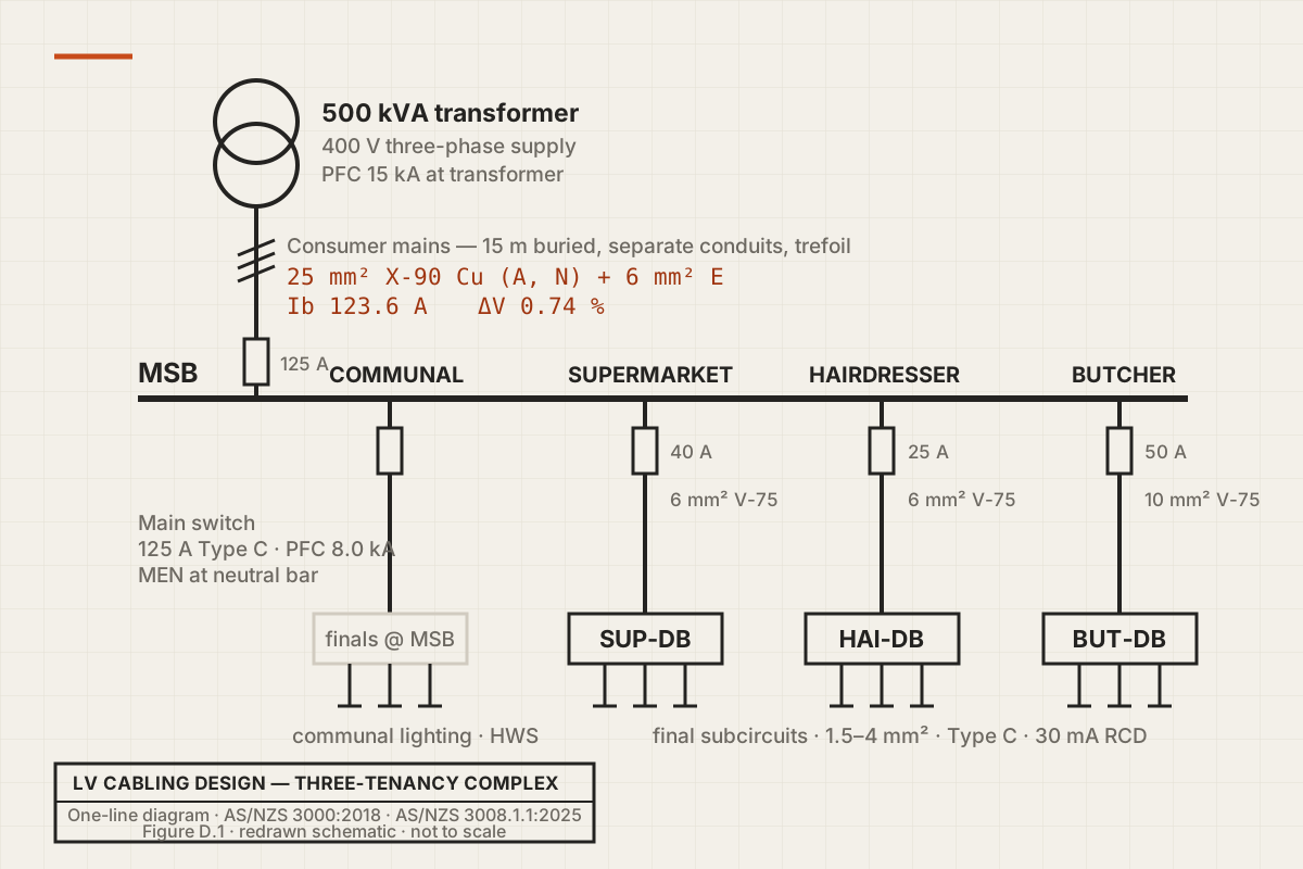
Open the full-size diagram (opens in a new tab)
Problem
What needed solving
Design the complete LV cabling system for a three-tenancy commercial complex supplied at 400 V from a 500 kVA transformer, and prove every cable and protective device against AS/NZS 3000:2018 and AS/NZS 3008.1.1:2025.
Approach
How the work is framed
Calculated per-phase maximum demand by the AS/NZS 3000 Clause 2.2.2(a) method, then ran one auditable nine-step selection chain per cable covering current capacity, de-rating, voltage drop, fault level, and earth-fault-loop impedance, with every assumption logged for verification against the controlling standard.
Result
Current public outcome
123.6 A design current met by 25 mm² X-90 copper consumer mains at 0.74 % voltage drop; 8.0 kA prospective fault current at the main switchboard confirmed 10 kA-rated Type C protection; every final subcircuit passed the AS/NZS 3000 Table 8.1 earth-fault-loop limits.
Evidence status
What still needs proof
Verified. Sanitised public write-up complete, including the full nine-step selection chain and the per-subcircuit results table; standards table data is cited by table number rather than reproduced (Standards Australia copyright).
Design detail
The full selection chain
Every cable in this design was selected with the same auditable nine-step chain: design current, protective device, installation method, correction factors, cable selection, voltage drop, fault withstand, earth-fault-loop check, final selection. The worked results below are my calculations; standards table data is cited by table number, not reproduced, because those tables are Standards Australia copyright.
Design basis
Three-tenancy commercial complex (a small supermarket, a hairdresser and a butcher, plus communal services), supplied at 400 V three-phase (230 V line-to-neutral) from a 500 kVA transformer with a stated prospective fault current of 15 kA at the transformer. Cable selection to AS/NZS 3008.1.1:2025; installation, earthing, protection and maximum demand to AS/NZS 3000:2018 (+ Amdt 1–3, Ruling 1:2024).
Maximum demand and phase balance
Maximum demand was determined by calculation per AS/NZS 3000:2018 Clause 2.2.2(a), using the Table C2 non-domestic diversity method. Every load was classified once, allocated to a phase, and group-diversity rules applied per phase; three-phase loads add their per-phase current to all three phases. The heaviest phase sets the design current: 123.6 A on phase A, with 7.5 % phase imbalance. Per board: communal 39.9 A, supermarket 39.1 A, hairdresser 24.5 A, butcher 41.8 A. The butcher is simultaneously the heaviest-loaded and longest (15 m) submain.
Consumer mains: worked chain
X-90 single-core copper, separate conduits laid in trefoil, buried 600 mm, soil 20 °C, 15 m route. AS/NZS 3008.1.1:2025 Table 3.8 routes this arrangement to Table 3.13, Column 19 (separately enclosed).
Step 1  Design current    Ib = 123.6 A (heaviest phase)
Step 2  Protective device In = 125 A Type C   (Ib ≤ In)
Step 3  Install method    Table 3.8 → Table 3.13, Col 19
Step 4  Correction        k = 1.04 (soil, T3.45) × 0.99 (depth, T3.46)
                            = 1.03
        Required tabulated CCC ≥ 125 / 1.03 = 121.4 A
Step 5  16 mm² → 101 A (fail);  25 mm² → 132 A (pass)
        Iz = 132 × 1.03 = 136 A → Ib 123.6 ≤ In 125 ≤ Iz 136  OK
Step 6  Voltage drop (limit 1 % = 4.0 V), Rc = 0.927 Ω/km
        ΔV = √3 × 123.6 × 15 × 0.927 / 1000 = 2.98 V = 0.74 %  OK
Step 7  PFC at MSB = 8.0 kA; breaking capacity 10 kA  OK
SELECT  25 mm² X-90 Cu active and neutral; 6 mm² Cu earth
A single-conduit arrangement (Column 17) would instead require 35 mm²; that is not the arrangement specified. The result is current-carrying-capacity driven, not voltage-drop driven.
Submains: worst case worked
V-75 single-insulated copper, one conduit, buried 1 m, soil 20 °C. Table 3.8 routes this to Table 3.12, Column 17. Combined correction k = 1.05 × 0.95 = 1.00. The butcher submain governs.
Step 1  Ib = 41.8 A          Step 2  In = 50 A Type C
Step 4  k = 1.00 → required CCC ≥ 50 A
Step 5  6 mm² → 45 A (fail); 10 mm² → 59 A (pass); Iz = 59 A
        Ib 41.8 ≤ In 50 ≤ Iz 59  OK
Step 6  ΔV = √3 × 41.8 × 15 × 2.23 / 1000 = 2.42 V = 0.61 %  OK
SELECT  10 mm² V-75 Cu; 4 mm² Cu earth
        (16 mm² recommended for practical margin)
Final subcircuits: the thermal-insulation catch
The specification states thermal insulation in all ceiling spaces, and the final subcircuits clip across the ceiling joists, so the cables are not in free air. A cable clipped to a structural member within bulk insulation is a partially-surrounded thermal-insulation installation under AS/NZS 3008.1.1 Clause 3.4.3. Ratings were therefore read from the partially-surrounded column with the 45 °C ambient correction (Table 3.44, factor 0.93). This condition raised most power circuits from 2.5 mm² to 4 mm², the single most consequential installation-condition decision in the design.
| Load type | Run (m) | Ib (A) | In (A) | Cable | Iz (A) | ΔV | Earth |
|---|---|---|---|---|---|---|---|
| Lighting | 26 | 5.0 | 10 | 1.5 mm² | 11.2 | 1.87 % | 1.5 mm² |
| Power (10 A GPO) | 24 | 10 | 20 | 4 mm² | 21.4 | 1.17 % | 2.5 mm² |
| Power >10 A (15 A socket) | 15 | 15 | 20 | 4 mm² | 21.4 | 1.10 % | 2.5 mm² |
| Hot water service | 18 | 15.7 | 20 | 4 mm² | 21.4 | 1.37 % | 2.5 mm² |
| Cooking appliances | 15 | 11.3 | 16 | 4 mm² | 21.4 | 0.83 % | 2.5 mm² |
| Air-conditioning (3-ph) | 10 | 4.6/ph | 10 | 2.5 mm² | 15.8 | 0.18 % | 2.5 mm² |
| 3-phase 15 A outlet | 10 | 15/ph | 20 | 4 mm² | 21.4 | 0.36 % | 2.5 mm² |
All Iz ≥ In and every voltage drop is within budget; the worst-case total path (mains + butcher submain + lighting final) sums to 3.2 % against the 5 % limit.
Earthing and protection
Protective earthing conductors were sized from AS/NZS 3000:2018 Table 5.1 on the MEN system, main earth connected at the MSB neutral bar. Because the 25 mm² consumer-mains active was set by current-carrying capacity and not upsized for voltage drop, the 6 mm² main earth follows directly from Table 5.1. Type C circuit breakers were used throughout (suited to the low inrush of LED lighting, resistive heating and small motors), with 30 mA RCDs on all final subcircuits up to 32 A supplying socket-outlets and lighting. Nominal-current grading (125 A, then 40 to 50 A, then 10 to 20 A) gives current discrimination; full selectivity is to be confirmed against manufacturer time–current curves, a stated limitation of scope.
Fault level and earth-fault loop
Source impedance  Zs = 400 / (√3 × 15 000) = 0.0154 Ω/phase
Consumer mains    R  = 0.884 × 15 / 1000   = 0.0133 Ω
Z at MSB   = 0.0154 + 0.0133 = 0.0287 Ω
PFC at MSB = 230 / 0.0287    = 8 014 A = 8.0 kA
All device breaking capacities (10 kA) exceed the local prospective fault current. Earth-fault-loop impedance was checked for the longest circuit of each conductor size against AS/NZS 3000:2018 Table 8.1 for Type C breakers; the worst-case loop (4 mm² general-power final, 24 m, on the butcher submain) gives Zs ≈ 0.57 Ω against a limit of ≈ 1.15 Ω. The external loop impedance Ze = 0.0345 Ω is a declared assumption; the real figure comes from the network operator's connection-point fault data or an on-site loop-impedance measurement.
Declared assumptions and limits
Assumptions are logged explicitly rather than hidden: the socket-outlet diversity basis, the consumer-mains conduit arrangement (Column 19 basis confirmed against the controlled 2025 edition at transcription), the assumed Ze above, and discrimination pending manufacturer curves. The partially-surrounded ratings used were cross-checked against the 2017 edition and confirmed unchanged in the 2025 edition. Final values are to be verified against the controlling standards and network authority at installation. This write-up is sanitised from graded coursework: the design scenario is paraphrased, and no standards table content is reproduced.
Questions about this design? nathannoott@gmail.com